




Reservoir Level and Flood Discharge

Radar and ultrasonic level units track reservoir and spillway water levels, with pressure at the discharge pipeline, so gate decisions rest on live readings.

IndustryWater resources
LocationSouth China
MeasuredReservoir level · Spillway level · Discharge pipeline pressure
Instruments4 models on one network

Overview

Reservoir operations depend on knowing the water level now, not at the end of a shift. Level is read at the reservoir body and again at the spillway, and pressure is read on the discharge pipeline that carries water away during flood release. These three readings move together when inflow changes.

The measurement points are far apart and some are unpowered. A single sensing method does not fit every point: a radar unit suits a narrow stilling well, an ultrasonic unit suits an open channel, and a pressure transmitter suits the pipeline. Operators wanted one stream instead of three separate records.

Challenges

Points far apart

Level is read at the reservoir body and again at the spillway, and pressure on the discharge pipeline: three places that move together but were recorded apart.

Some points unpowered

Some measurement points have no power and no cable, so each one has to carry its own supply and its own radio.

One method does not fit all

A stilling well, an open channel and a pipeline each need a different sensing method before the readings can be compared.

Solution

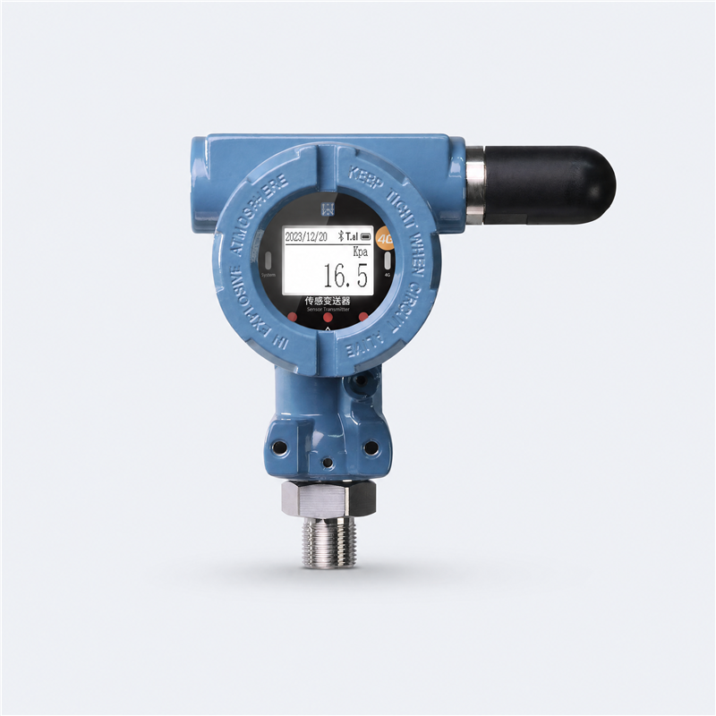
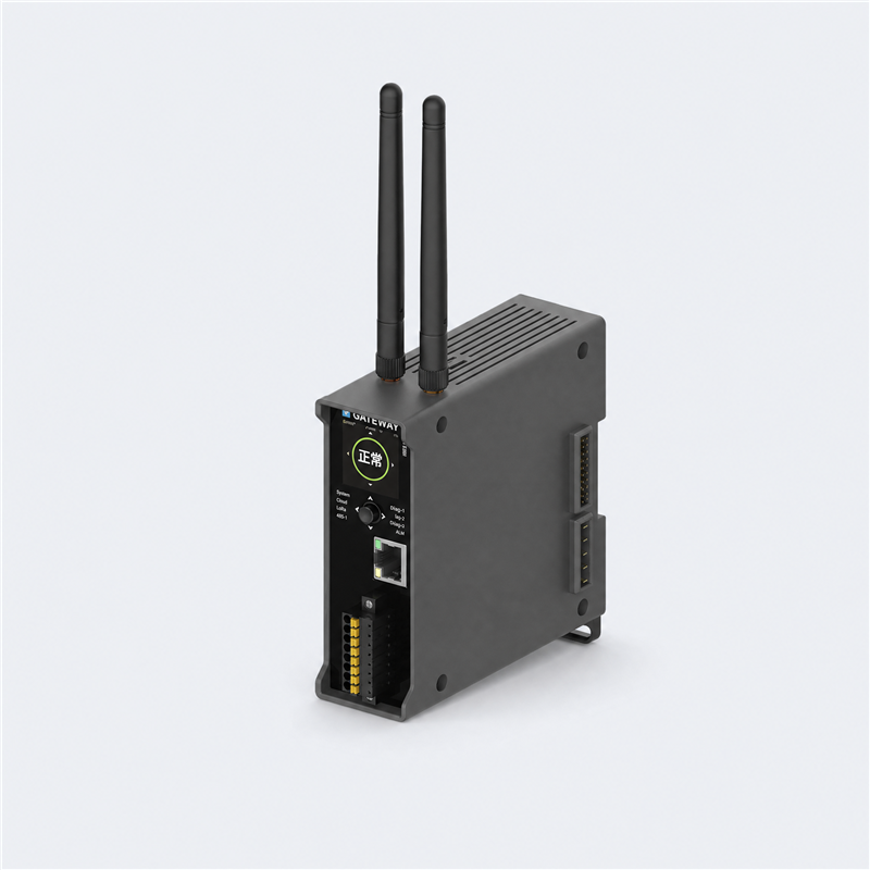
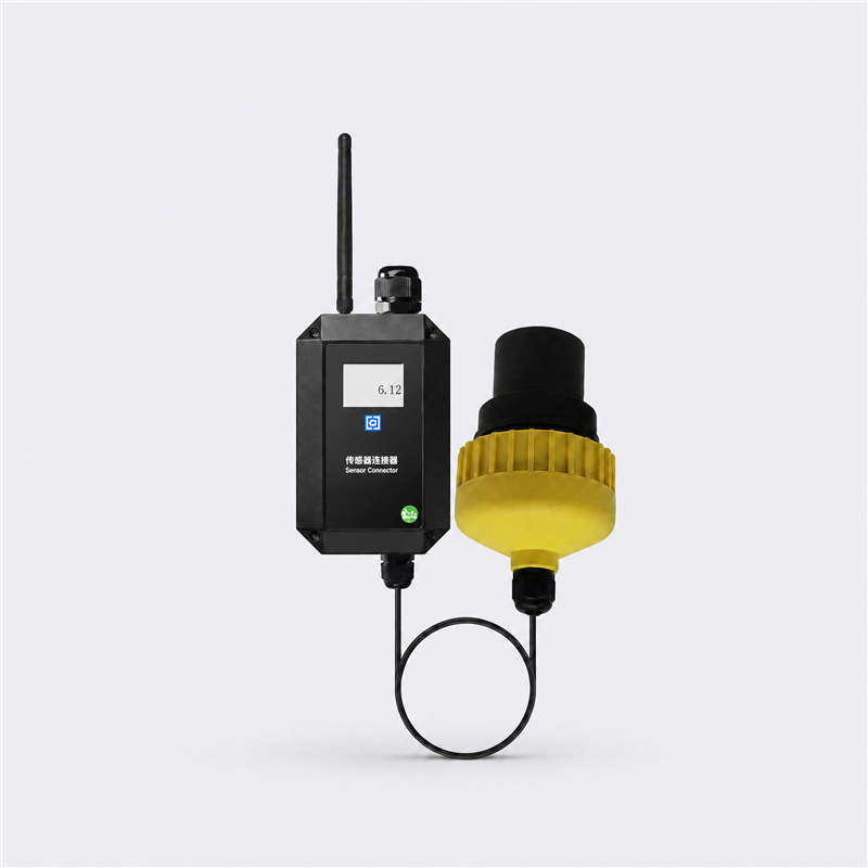
Level units sit at the reservoir and the spillway; the pressure transmitter sits on the discharge pipeline. Each one reports through the WES-WIO wireless terminal protocol to the WE-X280 edge gateway, which converges the wireless nodes and any wired device on site.

From the gateway the data goes over 4G or Ethernet to the WES device management platform. Threshold overrun, abnormal change and low battery are checked on the path, and the platform raises SMS and email notices when a level or pressure reading crosses its configured limit.
1

Measured points

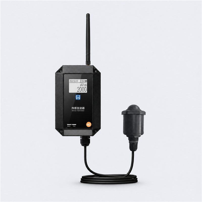
WE-T161 Reservoir levelWE-T160 Spillway levelWE-T130 Discharge pressure
2

Network and gateway

WE-X280WES-WIO wireless terminal protocolLoRa 410-490 MHz or RS4854G or Ethernet uplink
3

Platform and reporting

WES device management platformThreshold and abnormal-change alarmsSMS and email noticesTrend history and records
Reference topology: Reservoir Level and Flood DischargeFour layers. Measuring points in the field; the edge gateway carrying LoRa, RS485 and the WES-WIO wireless terminal protocol; the WES device management platform; and alarm delivery by SMS and email.WES delivered systemREPORTINGAlarm deliveryThreshold, abnormal change and low batteryreach the duty engineer by SMS and emailRecordsReadings and events kept as one timelinefor review and reporting4G or Ethernet uplinkPLATFORMWES device management platformPer-point thresholds, reporting cycle and alarm rulesTrend view, device health and user managementWES-WIO wireless terminal protocolNETWORKEdge gateway and uplinkWE-X280LoRa and RS485 nodes converge hereOne uplink carries the site outwardWireless terminal linkWES-WIOEvery probe reports over WES-WIOWired devices join the same gatewayPOINTSReservoir levelWE-T161Radar level reading on the main reservoir point;IP67 housing and LCD for site checks.Spillway levelWE-T160Ultrasonic level over a 0-8m range suits an openspillway channel.Discharge pressureWE-T130Protection-rated body with a 0-1.6MPa range forthe discharge pipeline.

Results

Three points, one viewReservoir, spillway and pipeline readings arrive on a single platform view.
Level trend between roundsContinuous readings replace the single level noted during operator visits.
Remote alarm deliveryLimit events reach staff by SMS and email, without a site visit.

Recommended Products

Next Step

Planning a deployment like this?

Tell us the sites and the discharge arrangement. We will pick the level method for each point and size the uplink.

Talk to an engineer